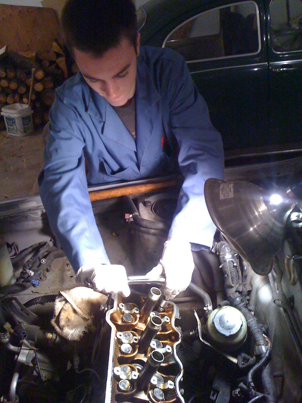
22. Jumped right into it and began to remove the cams. Adjusted timing gear to 10 degrees BTDC to engage the lobes on the 2 & 4 cylinders equally on the valves, then removed the cam timing gear with a generic pulley spinning tool from Harbor Freight for $10 (not pictured) which retains the gear while removing the 14mm retaining bolt.

23. Inserted a retaining bolt into the sub-gear and main gear on the exhaust side cam shaft (visible in the upper picture (shiny silver bolt to the right of the spark plug tube). I used an M6x20, 1mm pitch bolt and could have used something a bit shorter like an M6x16. Removed the end cap bolts per pattern and then the bolts on the 1, 2 & 4 cylinders per indicated pattern. Then removed bolts on #3 cylinder, backing out each slowly to ensure the cam being pushed out the the spring tension stayed level. On our first attempt, it began to lift at an angle. The Toyota tech manual made a big deal about the cam staying level so we bolted everything back up, adjusted the angle of the intake cam to about 15 degrees BTDC and repeated the exercise. The exhaust cam came out level this time.


24. Repeated the process for the intake cam, rotating it so the lobes on the 1 & 3 cylinders were evenly compressing the valves and removed the cap bolts on 1, 3 & 4 cylinders per indicated pattern. Then removed the bolts on #2 cylinder and the cam pushed out evenly on the first try. You'll notice the #4 spark plug tube is missing. The bolt adjacent to it began to strip so removed the tube (it was leading anyway and would have to remove it and reseal with Loctite) so I could get a Bolt Off tool on it.

25. Finally, what we've been excavating for the last month...removed the head bolts per indicated pattern. Had to explain to the boys the importance of following the pattern to avoid a warped head. Head pulled off easily once wedged free with a pry bar agains the pry point on the block.

26. Once we had the head on the bench, we inspected the bolts and gasket looking for the leak point. Could not conclusively identify it (admittedly I don't know what I'm looking for...). I did notice one area between the 2 & 3 cylinders on the exhaust side. The margin between the clean metal on the gasket and the discolored area was much thinner and the bolt removed from the hole adjacent to it (#9) had a lot of carbon buildup/crud on it.
 |
| Hard to see but area at 6 o'clock between 2 & 3 cylinders had a thin margin between the clean gasket and the discolored area. Bolt on the left below came from the hole closest to this spot. |

Waiting for the OEM gaskets and head bolts to arrive. Time to watch the Packers/Falcons playoff game...
No comments:
Post a Comment