Sunday, November 27, 2011

Gasket question...

48. Reassembling the water manifold and the OEM gasket is just a thin piece of stamped metal. Do I apply sealant to it or install dry? Can't imagine it's going to seal if it's dry...


Saturday, November 19, 2011

Figured 'r out!

44. Was still stumped over the mystery bracket from the last post when I decided to peruse the photos from the dis-assembly...whadd'ya know! Found one that showed how the bracket attached from the passenger side axle shaft to the lower bolt holding the power steering pump bracket to the block, as shown below.


45. Installed the center engine support member. Had to spend some time figuring out how the insulators rings and washers went back together (bolts closest in the picture). There is a bushing that installs with the bolt that limits the compression of the insulator. I'm realizing now I should've taken a picture. Sorry...


46. Installed the fore and aft engine mount insulators. You can see the end of the bolt in the middle-top of the picture.


47. Installed the engine cross member support. I'd forgotten how hard these were torqued...154 ft/lbs. Had to put my foot into it!


That was it for last weekend. I'll be doing some more later today and will post updates.

Monday, November 7, 2011

43'ish... Okay, mea culpa...I've been harboring a number of photos on my iPhone from the summer on the various steps I've taken to get the engine back in the car and reassembled. And then my phone died...sorry to say I've lost all of them. A thousand apologies since there were a few key steps I wanted to illustrate. Overall, the install was in reverse order. There were a couple of things I jury rigged I was hoping to illustrate however that I'll describe below with some new pic's where I can:

Clutch alignment - I decided to use the old clutch disc as it appeared newer and still had about 35 mm of material above the rivet head. I could not buy an alignment tool separately in town and didn't want to wait for an online order so I found a piece of 1 inch soft wood dowel in my scrap wood pile to use as alignment tool. I gently pounded the dowel with a mallet into the spline gear on the clutch place until it engaged the flywheel and then bolted it onto the flywheel. Then I flexed the dowel slightly up and down and worked it out of the spline gear. It worked perfectly as the spline on the transmission slid home after a couple attempts.

Driver side drive shaft - I scratched my head over this one while reading through the posts on TN on how to reinstall it. The challenge is the clip on the end of the shaft that has to overcome a spring inside the transmission to get it to drive home. It's virtually impossible to apply any force from the shaft by pushing it or using a mallet. Following photo's illustrate what I did. Since I snapped these after the fact, they are just for illustration purposes as the axle is already installed:

I started on top by slipping a crowbar down between the shift linkage on the tranny. Below are before and after shots so you can see where the bar was placed for leverage.


On the shaft, I spun the clip on the end of the spline gear so the split in the clip was at 6 o'clock (per instructions from other post). I carefully inserted the spline of the shaft into the transmission, taking care not to rub against the new seal so not to damage it. I then placed the blade end of the crowbar against the notch on the shaft. Using the leverage against the linkage, I pulled the top of the crowbar towards me. The blade against the notch on the shaft slipped a couple of times but once I was able to get it seated well, it popped the shaft home with ease. Not much force was required. Photo below shows where the blade goes against the shaft, taken from the outboard side of the shaft. Because this was taken after the fact, there is a protection shield on top of the shaft in the picture that was removed when I did the procedure, which allowed the blad to seat against the top of the shaft. Hope it makes sense:


Engine in car - The last photo for this post is the engine in the car. It's tough to appreciate how much cleaner it is than when we pulled it. If you look at some of older posts, this thing was a greasepit from all the leaking gaskets and blown seals. The steering rack appears to be leaking and I'll probably hold off on that until I know the engine is working and we get this baby on the road.


Photo's below are for a bracket that I've forgotten where it goes. The second photo is for the passenger half-shaft. I thought the bracket attaches to the shaft bearing housing but I can't seem to figure out how. Any thoughts?


Engine cross members go back in today. Promise I'll get back on track with uploading as I go. This last summer and fall have been crazy busy so it was hard to stay on top of it.

Friday, May 13, 2011

Back in the game!

42. After a long hiatus and the wife getting on me to get this POS out of the garage...jumped back in to start swapping parts. Did some serious scrubbing on the bell housing to get the baked on sludge cleaned up. My guess is the gearbox was overfilled and blew the shaft seal. It has been probably leaking for a long time...

Before...


After...


Needed to replace the input shaft seal and was scratching my head on how to remove it do it without pulling the gearbox. Looked up past posts on Toyota Nation and found a discussion on how to remove it. Used a self tapping sheet metal screw and drilled it into the seal, taking care not to scratch the aluminum housing.


Fit my flat bar under the head of the screw and gave it an easy shove...


...and shizzle...popped that baby out!


Nice...Toyota Nation comes through again!

Sunday, March 13, 2011

Day 2 of engine swap

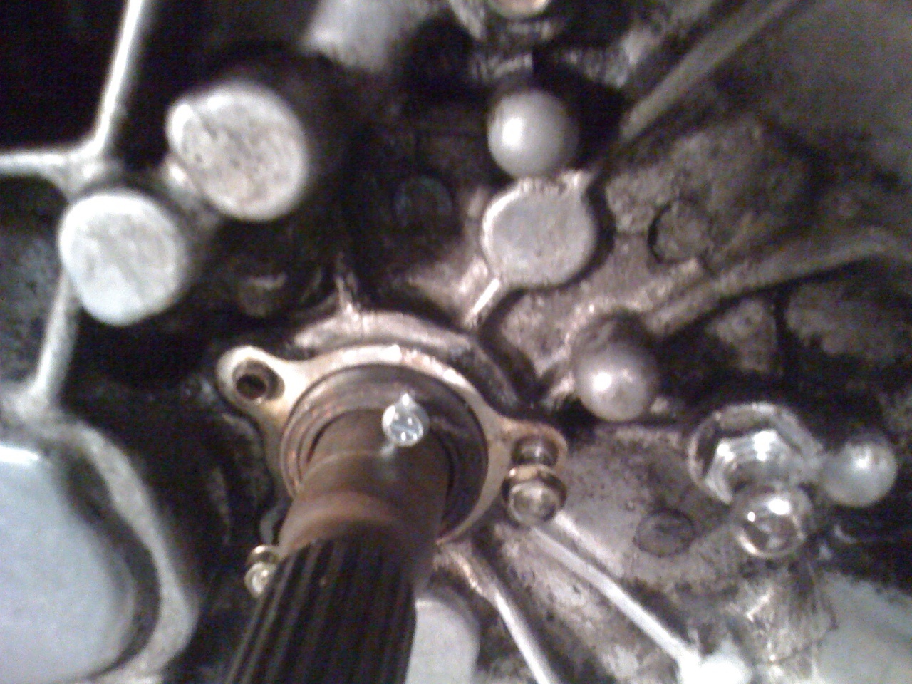
34. Received feedback from the Toyota Nation crew that the drivers side axle is removed by prying on it with enough force to overcome a snap clip on the axle. We bolted the cover plate back on and gave it a few yanks with the pry bar and it finally popped out.


35. Removed center bolt on the rear mount (round). Also removed the two bolts attaching the flange to the block from the rectangular rubber mount (not pictured), then dropped the center frame member (greasy piece of metal running left to right in the photo).


36. Went topside and we removed the starter.


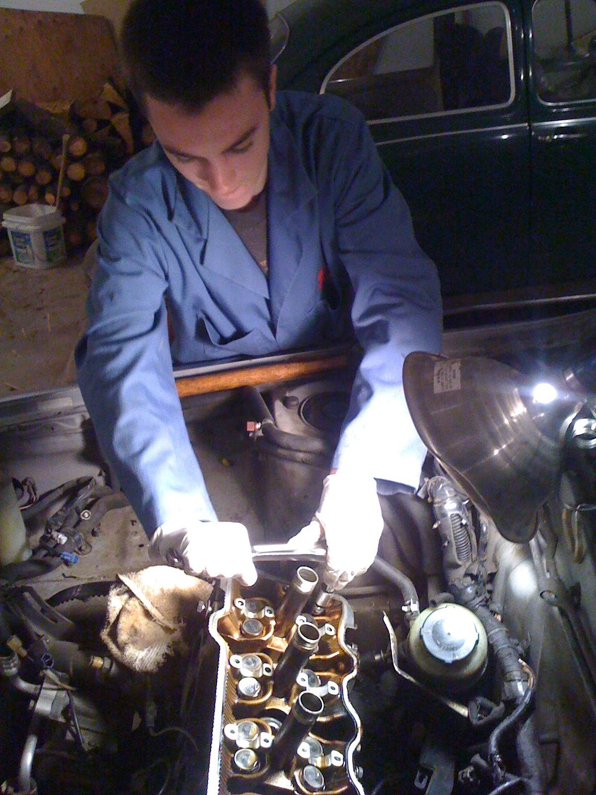
37. Began lifting on the motor with the engine picker. It kept hanging up on something in back though and my 14 year old finally spotted the culprit...had forgotten to remove the power steering pump on the rear, passenger side of the block (not pictured). Once we removed the mounting bolts for the pump, the engine/tranny moved freely. We hung it with the block end slightly higher since the end of the tranny needed to clear the engine mount bracket which cannot be removed. Taking care to push the various hoses and wiring harness out of the way, the engine lifted out easily. Success!!


38.  Placed the unit on blocks and began to remove the bolts attaching the engine block to the tranny. There were multiple sizes of bolts to be removed, 17mm, 14mm and 12mm, keeping track of which went where. Once all were removed, used a flat bladed screwdriver to split the seam. Keeping the block hanging from the picker, we pushed the block away and it separated easily.


39. Removed the clutch assembly. Remembered from the old days removing the clutch in the bug (in the college dorm parking lot no less!) to back out the bolts evenly to relieve compression on the clutch spring.


40. Removed the flywheel. Definitely could see evidence of a leaking crank seal, both behind the flywheel and on the tranny bell housing. Spent a few hours this afternoon with a scraper removing the thick gooey sludge from the bell housing/transmission. Will take it down to the car wash to soak it in degreaser.


41.  The JDM short block showed up last week at a friends shop that had a dock height door. Will be picking it up later next week and begin the component swap process. We need to decide what to replace and what to re-use from the old engine. So far am thinking:

  • New front and rear motor mounts
  • Clutch disk & throw out bearing
  • Timing belt & water pump
  • Crank seals (both sides)
Not sure about the axle seals...didn't see evidence of leaking but probably wouldn't hurt. Any other items I'm missing? (Keeping in mind I already have the full set of gaskets from when this was just a head gasket job...).


Monday, March 7, 2011

Day 1 of engine swap

27. Now that we are resolved to replace the engine with a short block, started removing components to get the motor and transaxle out of car. First step was removing the radiator. Pretty easy...disconnected the hose at the bottom and removed the two bolts at the top.


28. Removed the three bolts attaching the AC compressor to the block. Hog tied it to the front of the car to keep it out of the way when we lift the block out.


29. Removed the clutch slave cylinder. In spite of warnings to not disconnect the line with the fluid, I accidentally stepped on the clutch pedal tonight and it shot the piston right out of the cylinder, pissing brake fluid all over the garage floor. The fluid looked dark and contaminated, probably needing to be flushed anyway so I'm convincing myself it was a blessing in disguise...


30. Removed the transmission linkage cables. There was so much crap built up on the housing that I couldn't tell how to remove the cables. Finally figured out the angled flanges at the top of where the cable mounted on the housing were actually clips that pulled out. Was able to pull them free with a couple of good yanks.


31. Now we had to dive under the car to remove the axles from the transmission. Drained the transmission fluid and then sent my 14 year old under the car to remove the bolts from the driver side axle. The lower bolts were easy to access with a box end wrench however had a tougher time with the upper bolts. Realized there was a shield in the 10 o'clock position that we removed and gave us access to the other two bolts.


32. The tech manual instructions showed removing the knuckle mounting bolts from the driver side wheel assembly to be able to swing the assembly outboard, giving space to pull the axle out of the transmission. Not even...wouldn't budge. Gave up on the driver side for awhile and we attacked the passenger side axle. Removed the large e-clip and the bolt retaining the bearing as well as the mounting bolts holding the bearing housing to the block. Removed the knuckle mounting bolts on the passenger side wheel assembly and swung it outward which gave us room to pull the axle from the transmission. It pulled out from the spline gear just fine.


33. Okay, back to the driver side. Was able to get the outer cover backed out a bit but couldn't get it to budge any further. Will have to show this to the Toyota Nation forum to ask what they think.


Saturday, February 26, 2011

Cracked head...aka brick wall...

Okay...back in action after the long radio silence. Got an email from a guys down under in Ausy'land and the discussion reminded me I hadn't updated the blog for awhile. To make a long sordid story much shorter...sent the head to a machine shop in Portland to get resurfaced and they called me right back with the lovely news that the head had a freeze crack. Further, to put a new/rebuilt head on a block with near a quarter million miles on it...well, let's just say we're not going there. Sooo...back to square one with my original questions on the TN post...I've decided to plunk in a JDM. Found one in the Bay area with 50K miles on it for $520 delivered. Still a bit nervous about buying it site unseen. Have also found one locally in Portland for $500 with 130K miles on it with confirmed compression at 190 across all cylinders. Thoughts anyone?
In the meantime, I've borrowed an engine picker from a buddy and we are getting ready to hoist the ol' POS out. Stay tuned...


The crack is circled in the pic...runs vertically from the two coolant jacket chambers...

Saturday, January 15, 2011

Day 5

Back to it after a weekend off.

22. Jumped right into it and began to remove the cams. Adjusted timing gear to 10 degrees BTDC to engage the lobes on the 2 & 4 cylinders equally on the valves, then removed the cam timing gear with a generic pulley spinning tool from Harbor Freight for $10 (not pictured) which retains the gear while removing the 14mm retaining bolt.


23. Inserted a retaining bolt into the sub-gear and main gear on the exhaust side cam shaft (visible in the upper picture (shiny silver bolt to the right of the spark plug tube). I used an M6x20, 1mm pitch bolt and could have used something a bit shorter like an M6x16. Removed the end cap bolts per pattern and then the bolts on the 1, 2 & 4 cylinders per indicated pattern. Then removed bolts on #3 cylinder, backing out each slowly to ensure the cam being pushed out the the spring tension stayed level. On our first attempt, it began to lift at an angle. The Toyota tech manual made a big deal about the cam staying level so we bolted everything back up, adjusted the angle of the intake cam to about 15 degrees BTDC and repeated the exercise. The exhaust cam came out level this time.


24. Repeated the process for the intake cam, rotating it so the lobes on the 1 & 3 cylinders were evenly compressing the valves and removed the cap bolts on 1, 3 & 4 cylinders per indicated pattern. Then removed the bolts on #2 cylinder and the cam pushed out evenly on the first try. You'll notice the #4 spark plug tube is missing. The bolt adjacent to it began to strip so removed the tube (it was leading anyway and would have to remove it and reseal with Loctite) so I could get a Bolt Off tool on it.


25. Finally, what we've been excavating for the last month...removed the head bolts per indicated pattern. Had to explain to the boys the importance of following the pattern to avoid a warped head. Head pulled off easily once wedged free with a pry bar agains the pry point on the block.


26. Once we had the head on the bench, we inspected the bolts and gasket looking for the leak point. Could not conclusively identify it (admittedly I don't know what I'm looking for...). I did notice one area between the 2 & 3 cylinders on the exhaust side. The margin between the clean metal on the gasket and the discolored area was much thinner and the bolt removed from the hole adjacent to it (#9) had a lot of carbon buildup/crud on it.

Hard to see but area at 6 o'clock between 2 & 3 cylinders had a thin margin between the clean gasket and the discolored area. Bolt on the left below came from the hole closest to this spot.

Waiting for the OEM gaskets and head bolts to arrive. Time to watch the Packers/Falcons playoff game...

Sunday, January 2, 2011

Day 4

14. Removed the cruise control actuator and cables.


15. Jacked the engine slightly under the oil pan. I used a piece of plywood to distribute the load on the pan. Also removed the right wheel and plastic panels below the engine.


16. The Toyota manual didn't show it but the power steering reservoir and hoses restricted access to the timing belt cover so we unbolted the bracket and wrestled it over the top of the head cover to give us room.


Point of instruction I hounded the boys on...reinstall all removed bolts and nuts into the location they came from. Too often I've ended up with a coffee can full of loose bolts wondering where they go...


17. Removed through bolt on the engine mount. There are two 14mm nuts that you have to get at from below with a deep socket and 6" drive extension.


18. Removed spark plugs. The access tube for the #4 plug had about an inch of oil in it. Any thoughts on how the oil is getting in there?


19. Removed the upper timing belt cover. Rotated the crank until the notch aligned with 0 degrees TDC on the lower cover. Ensured the cam timing pulley (intake side...sorry couldn't take photo...too tight to get the camera in there...) alignment hole was aligned with the head (about 11:00 as you look directly at the face of the drive gear).


20. Marked the belt relative to position on the cam timing pulley and removed it from the pulley and idler. The instructions on the manual were not helpful here. It said to push the idler as far left as possible and retighten the bolt to retain in the loose position. It said nothing about having to remove the spring to allow the idler to move, which it did easily once we removed the spring from the upper pin (you can see the pin just below the idler. In this pic, the belt has been moved out of the way below the pin for clearance).


21. Removed the head cover and stopped here for the day. Manual noted to use a service 6mm dia/1mm pitch x 20mm length service bolt to secure the exhaust camshaft sub-gear prior to removal. Will need to pick one up and a spanner wrench to remove the camshaft timing pulley. Surprisingly, the belt looks pretty new. I'll have to go through receipts again to see how long ago they replaced it.